01/21/24, 01/28/24 and 02/04/21, 12h
Based on a review of the manuals and a few blocks, the following is the configuration of the antennas we are thinking to implement. This configuration is not final as we still need to further read the documentation of each antenna:

Generic info on antennas: https://www.aopa.org/training-and-safety/students/presolo/special/antennas
Performance considerations:
The physical condition of the antenna plays an important role in its performance. If the antenna is cracked, water may enter and cause delamination (a separation of the composite layers), which may render the antenna useless. And if the antenna base is not structurally strong, the antenna will vibrate from the slipstream and cause the skin to fatigue, eventually causing cracks.
The antenna must be electrically bonded (grounded) to the airframe so a good electrical connection is maintained. If some corrosion gets underneath the antenna, this bond may be compromised and the antenna’s efficiency may degrade. Sealant around the base of the antenna helps to prevent this. Antennas should never be painted over their original coatings; any paint buildup reduces the efficiency of an antenna.
Real estate is very scarce on an aircraft, and sometimes there is very little left for antennas. Every antenna location is a compromise between a solid mounting, shadowing, other antenna interference, ground planes, and aerodynamics.
Mounting and bonding:
- Many factors influence antenna performance. Of course the physical condition of the antenna plays an important role. If the antenna is cracked or the paint worn off, water may enter and cause delamination (a separation of the composite layers), which may render the antenna useless. Another problem deals with the underlying structure and electrical metal bonding. If the antenna base is not structurally strong, the antenna will vibrate from the slipstream and cause the skin to fatigue. Eventually this causes cracks and may rip the antenna off the fuselage, especially if there is ice buildup on the antenna. A riveted doubler plate under the antenna base prevents the vibration and work-hardening of the skin.
- The antenna also must be electrically bonded (grounded) to the airframe so a good electrical connection is maintained. If some corrosion gets underneath the antenna, this bond may be compromised and the antenna’s efficiency may degrade to the point that a com may only transmit a couple of miles. Without a seal around the antenna, water creeps underneath and causes corrosion in a very short time. This bonding is practically nonexistent if a mechanic uses a sealant under the antenna, trying to curb corrosion. The proper bond is a bare metal skin to antenna mating surface with sealant around the base of the antenna.
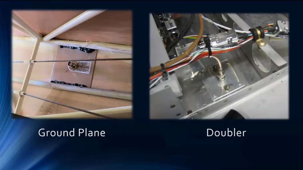
- In addition to a skin doubler and good electrical bonding, a transmitting antenna also needs an effective ground plane. To transmit correctly, a quarter wave antenna (the antenna is one-quarter the length of the electromagnetic wave) needs an electrically bonded structure around it with a radius equal to the antenna length. In other words, lay the antenna down and scribe a circle. This is the amount of metal (ground plane) that the antenna needs around it to work properly. Those of you with composite aircraft still need this ground plane, which often consists of a metal plate just inside the skin. For instance, if a com antenna is two feet long, it must have two feet of metal around it. Just a few of those transmitting antennas are the com, DME, transponder, ELT, radar altimeter, satellite telephone, and HF.
- Another problem is paint. Antennas should never be painted over their original coatings. Any paint buildup reduces the efficiency of an antenna. Transmitting antennas are particularly sensitive to paint problems, especially when covered with metallic paint
ADHRS
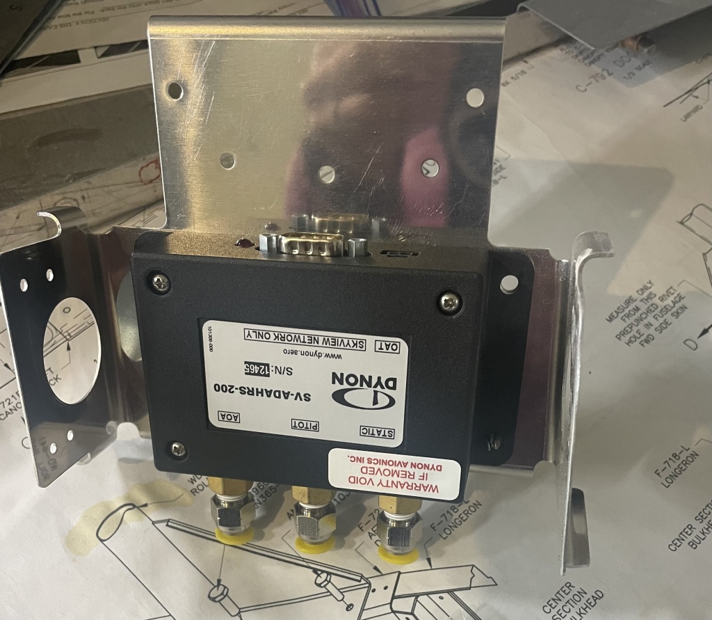
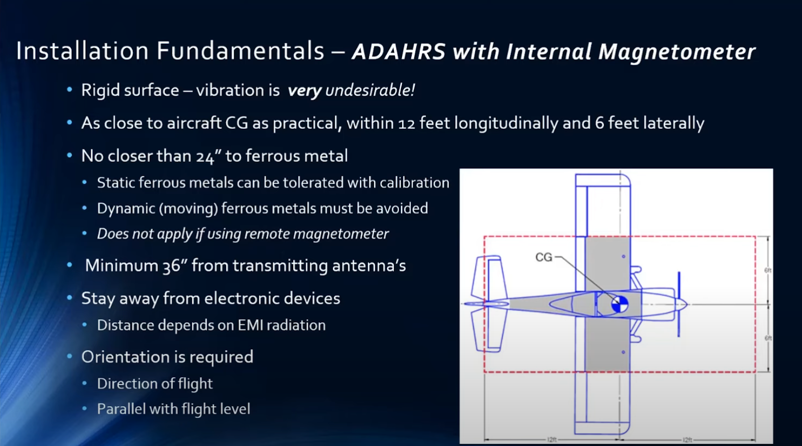
- Mount to the second bulkhead behind the baggage compartment to create 2 ft from the ferrous materials: https://www.vansaircraft.com/service-information-and-revisions/op-60/
- Align within one degree in all flight directions
- Use Brass hardware for mounting.
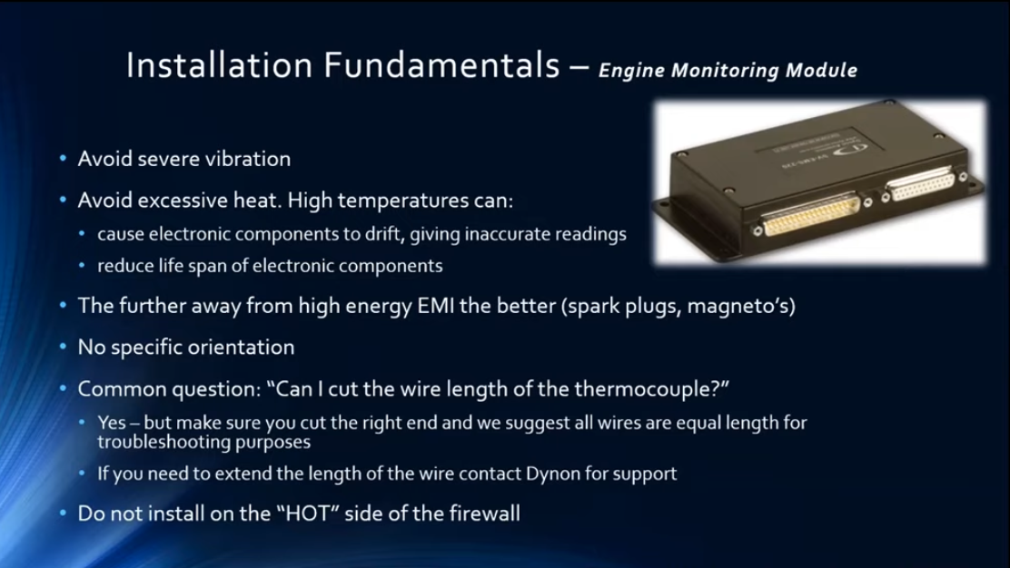
EMS (Engine Monitoring Module)
- Avoid flimsy aluminum mounts (limit vibration)
- The Hot side of the firewall will limit the lifetime of the product.
- Keep the EMS unit close to the engine to avoid long wires
- The second bay, as we have it in the mockup panel seems like a good location.
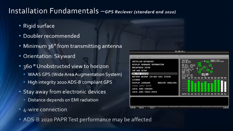
GPS receiver
- Don’t place near any transmitting antenna (ELT doesn’t matter because if the ELT does goes off, you won’t need the GPS anyhow because you will likely be in a crash on the ground)
- To test the system and make sure your GPS receiver is in a good place, you can bring the airplane outside away from hangars, and bring up the “GPS fix status” screen to see how many satellites you can see.
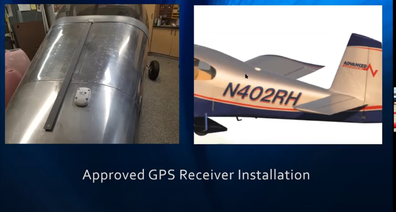
- Many people place the GPS receiver on the aircraft skin, this is fine, but install a doubler plate for a more rigid surface.
- Putting the GPS inside like the RV12 under a fiberglass cowling isn’t good ONLY because there is likely metal that obstructs the unit from a full 360 degree view.
- NOTE: The vertical stabilizer isn’t large enough to degrade much for performance so putting on the top rear of the aircraft is a good spot
- DO NOT place the receiver on the bottom of the airplane (bad quality)
- Don’t paint the receiver OR put a fiberglass part over the top
- Dynons ground plane is built into the unit and you don’t need to add an additional one
- Dynons receiver is the antenna as well. It’s an all in one unit(some others separate the unit)
Garmin antenna mounting requirements:
The GPS antenna is a key element in the overall system performance and integrity for a GPS/WAAS navigation system. The mounting location, geometry, and surroundings of the antenna can affect the system performance and/or availability. The following guidance provides information to aid the installer in ensuring that the most optimum location is selected for the installation of the GPS antenna. The installation guidelines presented here meet the intent of AC 20-138A section 16. The greater the variance from these guidelines, the greater the chance of decreased availability. Approach procedures with vertical guidance are the most sensitive to these effects. LNAV only approaches, terminal operations, and enroute operations may also be affected. Because meeting all of these installations guidelines may not be possible on all aircraft, these guidelines are listed in order of importance to achieve optimum performance. Items 3a, 3b, and 3c below are of equal importance and their significance may depend on the aircraft installation. The installer should use their best judgment to balance the installation guidelines.
- Mount the antenna as close to level as possible with respect to the normal cruise flight attitude of the aircraft. If the normal flight attitude is not known, substitute the waterline, which is typically referenced as level while performing a weight and balance check.
- The GPS antenna should be mounted in a location to minimize the effects of airframe shadowing during typical maneuvers. Typically mounting farther away from the tail section reduces signal blockage seen by the GPS antenna.
- The GPS antenna should be mounted no closer than two feet from any VHF COM antenna or any other antenna which may emit harmonic interference at the L1 frequency of 1575.42 MHz. An aircraft EMC check (reference VHF COM interference check in Post Installation Checkout procedures) can verify the degradation of GPS in the presence of interference signals. If an EMC check reveals unacceptable interference, insert a GPS notch filter in line with the offending VHF COM or the (re-radiating) ELT transmitter. Page 2-2 GA 35, GA 36, and GA 37 Antenna Installation Instructions Revision B 190-00848-00 Note: When mounting a combination antenna, the recommended distance of two feet or more is not applicable to the distance between the antenna elements in a combination antenna (ex. GPS and COM, GPS and XM) provided the combination antenna is TSO authorized and has been tested to meet Garmin’s minimum performance standards.
- To maintain a constant gain pattern and limit degradation by the windscreen, avoid mounting the antenna closer than 3 inches from the windscreen.
- For multiple GPS installations, the antennas should not be mounted in a straight line from the front to the rear of the fuselage. Also varying the mounting location will help minimize any aircraft shading by the wings or tail section (in a particular azimuth, when one antenna is blocked the other antenna may have a clear view).
- The GPS antenna should be mounted no closer than two feet from any antennas emitting more than 25 watts of power. An aircraft EMC check can verify the degradation of GPS in the presence of interference signals.
- To minimize the effects of shadowing at 5° elevation angles, the GPS antenna should be mounted no closer than 6 inches (edge to edge) from other antennas, including passive antennas such as another GPS antenna or XM antenna.
Comm Antennas
- Communications radios can cause a lot of interference with GPS, because of the proximity of the panel units or their antennas. Therefore, it is important that the com and GPS antennas be mounted as far apart as possible. Sometimes a com antenna must be relocated to the bottom of the aircraft.
- Communication antennas are basic in operation and have relatively few problems, except for delamination (more on that later). Each com transmitter has its own antenna, mostly for redundancy and a couple of technical issues. The antennas can be mounted on either the top or bottom of the aircraft, but each installation is susceptible to shadowing from the fuselage.
- Shadowing is caused by structure, such as fins or gear doors, in the transmitting path of the antenna. Know where your antennas are and how shadowing may affect their range and coverage. If you have com antennas on the top and bottom of the aircraft, it helps to determine which antenna feeds which radio. The radio that feeds the top antenna would be better for communications while the aircraft is still on the ground, and the antenna on the bottom would be better for communications while airborne, having a clear shot of the ground antenna site in each case. Some older Cessna twins have a com antenna buried in the vertical stabilizer, which limits their range and coverage.
ELT
They are almost always on the upper skin of the empennage and are made of a flexible material. There are a few exceptions, though; some may be buried in the vertical tail or look like small com antennas.
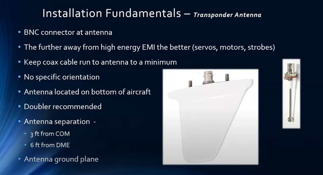
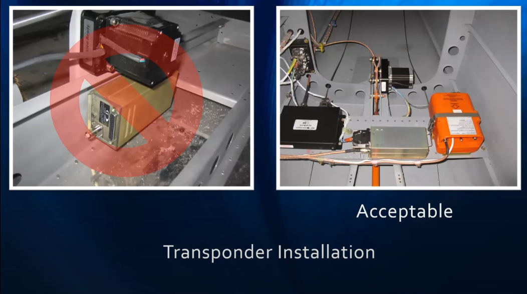
Transpander
- RG400 coax cable – do not bend it at any time more than 10x the radius. This can open up the mesh around the cable and there will be a degradation of the unit. (This can’t be undone and will need to be replaced)
- Mount transponder as close to the antenna as possible – better performance.
- This unit has a TNC connector not a BNC(bayonette vs a threaded): Buy a TNC to a BNC cable – they are common in the marketplace and not too expensive.
- The farther the transponder is away from high energy EMI the better (keep away from servos,motor, strobe lights
- Keep away from other transmitting sources. This unit is a higher transmitter
- Antenna needs a ground plane and likely doesn’t come with one
- Adding a doubler should work as a ground plane for you when attaching to the metal skin of the aircraft
- Square ground plane like shown below is just fine for mounting. Doesn’t have to be a circle
- Can running GPS wires with transponder, ADSB
- Shouldn’t be an issue. GPS is a low current device, shouldn’t have interference with the other items)
- Don’t run servo wires(high power) in this bundle
- UHF Antennas (Transponder)
- UHF antennas are commonly used for transponders and DMEs and are always found on the bottom of the aircraft. They are about four inches long, and the same antenna is often used for both systems because the transponder frequency is in the middle of the DME frequency band. Two types are commonly used, spike (Figure 5) and blade (Figure 6) antennas. The spike should only be used for transponders, because the antenna length is tuned to one frequency, the transponder frequency. The blade antenna is also called a broadband antenna because it is tuned for a range of DME frequencies. A spike would not work very well for a DME; the blade antennas are preferred because the radiation pattern is better and ice formation is less likely to break them.
- The spikes are prone to caking up with oil, reducing the transmitting range. Often, just cleaning a spike antenna doubles your transponder range and gets rid of those intermittent Mode C problems. The reason is that the ground secondary radars need only one sweep to determine your squawk code (Mode A), but they need two good sweeps to determine altitude information (Mode C). Hence, a dirty antenna may not conduct a good signal reliably. This goes for all antennas; a dirty antenna does not perform up to its potential.
- Transponder and ADSB antennas need to be at least 2 ft apart, further if you can – saw this in a dynon forum – who can verify?