Wing internals continue

November 2nd, 5h

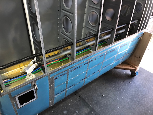
I continued on the prep for the wing riveting.  So, I finish all the pitot/AoA probe wiring:

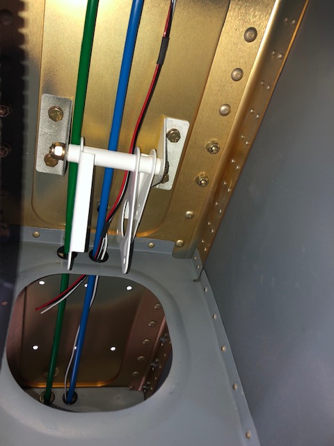
  • Attaching the wires from the probe to the controller with zip-ties and zip-tie attachments that I glued with E6000 to the control unit.
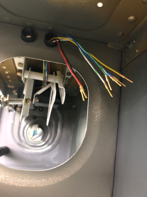
  • Extending the wires from the control unit by using 20 gauge wire of the same color and butt connectors
  • Applying a wire protection for all the pitot/AoA wires, as well as the stall horn wire.

IMG_1699.jpg

IMG_1700.jpg

IMG_1701.jpg

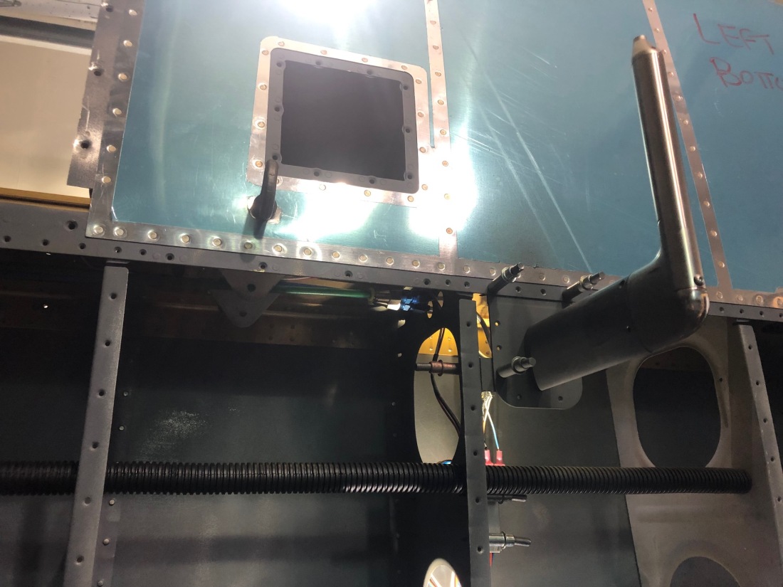
I also looked into attaching the pitot probe to the must with screw, but I had some trouble with tapping the holes.  I am consulting with Dynon on that, and my current plan is to fill those holes with JB weld and to make new ones.


Wing Internals

October 27th, 6h

We need to finish all the small details inside the wing in order to rivet the bottom skins and finish the wings.

  • So, I applied E6000 to the conduit.
  • We started setting up the wiring of the pitot, but then we realized that we need to buy more wire and connectors
  • We looked at the wiring for the lights, not much to do there. We tested passing it through the conduit, it worked great.
  • We wired the magnetometer through the conduit, it was pretty easy to drive through, and not much setup needed.
  • We wired the roll servo by making a connector and a cable for all the wires.  As well, we glued some zip-tie attachments to control routing the cable and relieve strain.

IMG_1690.jpg

IMG_1689.jpg

Overall, we are pretty close to finishing up all the small internal details of the wings, and move on to riveting the bottom skins.


Pitot, Roll Servo & BellCrank

August 3rd & 10th 13h

Pitot Tube

I followed on the work on the pitot heat assembly by riveting platenuts into the pitot heat controller. I decided to use platenuts, so that I will have an easy way to remove the pitot heat controller for service.

IMG_1397.jpg

Then, I decided to cut down the tubes for the pitot tube.  By having the tubes shorter, it will be way easier to remove the pitot tube in the future, for service.

IMG_1403.jpg

Bellcrank

As well, I worked on to the bellcrank assembly.  I received the bell crank bushing, so I had all the parts. I had to disassemble the tiedown in order to fit the bushing in.  Then I installed all the parts of the bellcrank and tightened everything to the torque settings, for both the left and right wings.

Following is the left bellcrank assembly with the pitot and AoA tubes and heat control wiring passing under the bellcrank.

IMG_1405.jpg

Following is the bellcrank of the right wing, with the modification for the roll servo. I still need to add safely wire for the bolts for the roll servo, for which I have just ordered the tool.

IMG_1406.jpg

Next, I primed all the roll control tubing, from both inside and outside.

IMG_1407.jpg

Roll Servo

For the roll servo, I finally received the crimping tool, so I crimped all the connections.

IMG_1401.jpgIMG_1400.jpg

Roll Servo

July 30th, 9h

I continued on the installation of the roll servo and tie down.  First I attached the tie down to both the left and right wing, with all new hardware, setting all the torques correctly with the new torque wrench.  Then I installed the roll servo into the right wing.  Afterwards, I moved on to attaching the bellcranck, and I discovered that Vans forgot to ship me the bell crank bushings, so I ordered them. Then I moved on to the wiring, but I did not have the proper crimping tool, so I ordered one.

IMG_1390.jpg

IMG_1389.jpg

IMG_1387.jpg

IMG_1388.jpg

July 13th, 14th, 16th and 23rd, 12h

To get started in the roll servo, I needed to first fix the tie down assembly that was over torqued.  So, I removed the tie down for both the left and the right wings, removed all the platenuts by removing all the rivets.  Then riveted new plate nuts. Then primed. Afterwards, I will be re-attaching the tiedown with new hardware.

IMG_1385.jpg

Then I moved on to the assembly of the roll servo.  I decided to attach the limiting bracket, to ensure that the servo will never get into the null space, which will cause loss of roll authority. Then I assembled the rest of the hardware, which went pretty smoothly.  Next is to attach the roll servo with the tie-down into the wings.

IMG_1383.jpg

IMG_1384.jpg

Pito Probe

July 6th, 10th 18h

I finalized by decision on the avionics and decide to go with Dynon. So, I got all the part for the wing: heated pitot probe with AoA, servo for aileron and magnetometer.

I got started by the pitot probe.  First I had to pick a place for the pitot probe. The option shown in the plans by Van does not work for the Dynon pitot probe because it will lead to interference between the aileron bell-crank and the pitot tube.  I decided to put the pitot probe just to the left of the bell-crank assembly, to avoid interference while still being as close as possible to the center, between wing root and tip.

Then, I mounted the pitot tube mast into the wing by cutting out the mast slot in the wing skin, and drilling the attachment holes in the mast and the wing skin. As well, I drilled the bracket that attaches the mast to the rib and the skin to support the required loads.

IMG_1364.jpg

Then I installed the pitot probe, which fits pretty well into the mast.  I drilled 4 holes for #6-32 screws to attached the the pitot to the mast.

As well, I attached the pitot heat controller into the rib, right under the pitot tube, so that I don’t need to add any extension to the wires.  The wires provided were more than plenty to reach between the pitot and the controller.

Then  I moved on to the plumbing:

  • I attached the wires between the pitot tube and the controller.
  • I fluted the aluminum tubing for both the pitot and AoA.
  • I connected the pitot and AoA aluminum tubing to the plastic tubing
  • I past the plastic tubing through the tooling holes. The bushing provided were made for a 3/8inch holes, but my tooling holes are 5/8inch, so I need to buy some new bushings.

IMG_1360.jpg

IMG_1361.jpg

IMG_1362.jpgIMG_1363.jpg